In the
televisions systems, signals can be carried between a limited frequency
spectrum, which a concrete lower and upper frequencies. A modulator is a device
charged of transporting a signal inside another signal to be transmitted. Is
able to transform a low-frequency signal into a other frequency signal. As a
result of, the frequency can be controlled and the problem above can be solved.
Mainly, the aim of modulate a signal consist in changing a parameter of the
wave according to the variations of the modulation signal (information to be
transmitted).
There are four modulation modes available, with
QPSK and 8PSK intended for broadcast applications in non-linear satellite
transponders driven close to saturation. 16APSK and 32APSK, requiring a higher
level of C/N, are mainly targeted at professional applications such as news
gathering and interactive services.
Adaptive Coding and Modulation (ACM)
allows the transmission parameters to be changed on a frame by frame basis
depending on the particular conditions of the delivery path for each individual
user. It is mainly targeted to unicasting interactive services and to
point-to-point professional applications.
DVB-S2 offers optional backwards compatible modes
that use hierarchical modulation to allow legacy DVB-S receivers to continue to
operate, whilst providing additional capacity and services to newer receiver.
Digital
modulation is often a means of transmitting payload data from orbiting
satellites to ground stations. In one
such approach, quadrature phase-shift-keying (QPSK) modulation provides both
spectral and power efficiency. In a QPSK modulator, two data streams
simultaneously modulate a carrier signal. For optimum use of available
satellite power, an unbalanced QPSK (UQPSK) modulator is often used. The design
and simulation for such a modulator will be shown here, along with methods for
demodulating such signals.
Communications channels in satellite-communications (satcom) systems, as
well as communications systems in general, can be categorized as being power-
or bandwidth-limited. For power-limited communications channels, coding schemes
are typically applied to save power at the expense of bandwidth. In
bandwidth-limited channels, spectrally efficient modulation schemes are often
used to conserve bandwidth. The prime goal of spectrally efficient modulation
is to optimize bandwidth efficiency, which is defined as the ratio of the data
rate to the channel bandwidth (in b/s/Hz). A secondary goal of such a
modulation scheme is to achieve high bandwidth efficiency with minimum signal
power.
QPSK modulation results in optimum use of both spectrum and power when
the data rates for the two channels—or the in-phase (I) and quadrature (Q)
signal components—are the same. But when two data streams at different bit
rates from two independent payloads must be transmitted, the normal procedure
of formatting the data for modulation onto the carrier becomes very
complicated. The easiest way is to transmit the two different data streams on
the two QPSK channels by direct modulation, which results in the two channels
of the modulator having different data rates. The higher of the data rates
determines the bandwidth required for the modulated carrier and the transmitter
output power will be equally shared by the two different data streams.
To optimize available transmit power from a satcom system, an UQPSK
modulator is proposed here, where the power level of the low-data-rate channel
can be reduced to achieve the same carrier-to-noise (Eb/No)
ratio for both channels. This can be achieved by unbalancing the amplitudes of
the carrier’s signal components in the I and Q channels of a conventional QPSK
modulator. The amplifier power following the modulator is shared between the I
and Q channels in proportion to the amplitudes of the I and Q signal components
of the modulated carrier.
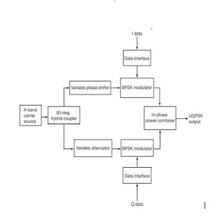
Figure 1 shows a block diagram of the proposed UQPSK
modulator. In a conventional QPSK modulator, the carrier source signal is
divided equally by a 3-dB/90-deg. branch line hybrid coupler to yield two
equal-amplitude carriers in quadrature. Both carriers are modulated with I and
Q data streams using binary-phase-shift-keying (BPSK)modulation. The
BPSK-modulated carriers are combined in an in-phase Wilkinson power combiner to
produce a QPSK-modulated carrier. When data of different bit rates are to be
modulated, an UQPSK modulator can be used.
1. This block diagram represents the proposed UQPSK modulator.
In the case of an UQPSK modulator, for optimum utilization of power, an
attenuator is added to the low-data-rate channel to reduce the power. A phase
shifter is added tothe high-data-rate channel to compensate for the phase shift
introduced by the attenuator in the low-data-rate channel. The resulting output
isa UQPSK-modulated signal. The mainlobe bandwidth will be determined by the
high-data-rate channel. Figure 2 shows a plot of the I and Q
data, along with the simulated UQPSK spectrum.


No comments:
Post a Comment